I’m an engineer. Despite that, I’m usually fine with following the proportions which most woodworkers use to lay out a joint. They are tried and true and (as an engineer) mostly seem reasonable to me. And I don’t have the woodworking experience to (generally) stray too far from whatever more experienced woodworkers suggest.
But I’m in the midst of laying out a tusked tenon joint for a dining table, and haven’t been able to find those sort of guidelines. And it’s for a critical joint, holding the legs onto my dining table. And I subscribe to Chris Schwartz’s attitude towards joinery – I want this to last several lifetimes. So I started digging into it.
For whatever it’s worth, here’s what I found. I’m going to get to proportions at the end, so you may wish to skip to there. (I’m writing it up so I can find it again too, but I do hope it’s helpful to others.)
The problem
Tusk tenon layouts don’t seem to be discussed much. Googling turned up a handful of useful and not useful links. This joint has been used in some very demanding places, e.g. the Moravian workbench, so if laid out correctly it’ll do.
But what are the right proportions? Especially, if the tenon isn’t long enough to house the key, it’ll split. And all I can find for that length is the advice to “make it long”.
H.Fukuyama et. al. wote a paper, aimed at single ended dowels in softer woods (cedar, etc). So, not really applicable to a pin (dowel) running through the tenon, as is typical in the drawbored or pinned tenon used by furniture makers (a.k.a. double shear). But I think his work is adaptable to the tusk tenon.
The typical loading – and certainly the one I am interested in – for the tusked tenon would be a racking load, as in when someone is dragging a table about. And in that case, the wedge is effectively in single shear, as in Fukuyama’s paper. That’s precisely the loading that I did not find any other usable papers on.
Lets think about this
H. Fukuyama et. al. include a thorough discussion of failure modes – compression of one member, compression of the other, shear of the pin, etc. I found his paper here: http://support.sbcindustry.com/Archive/2008/june/Paper_167.pdf?PHPSESSID=ju29kfh90oviu5o371pv47cgf3
(Disclaimer – I sure hope it was intended to be published to the public. I’m assuming it was and hence my use is fair use.)
Here’s an image showing the failures his group considered.
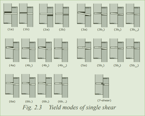
Failures where the dowel is embedded in one member or the other without deflecting (modes 1-3), and the dowel failing without damage to the members (mode 7), seem unlikely in this case. Those would occur when one member is substantially softer than the other. The in-between modes (4,5 and 6) seem likely in the current case (everything hardwood).
For a piece of furniture, I’m not interested in ultimate load. I am interested in any compression or distortion of the mortised or tenoned member, and any significant distortion of the wedge. Ultimate loads are higher, but I don’t want the joint loosening over time either.
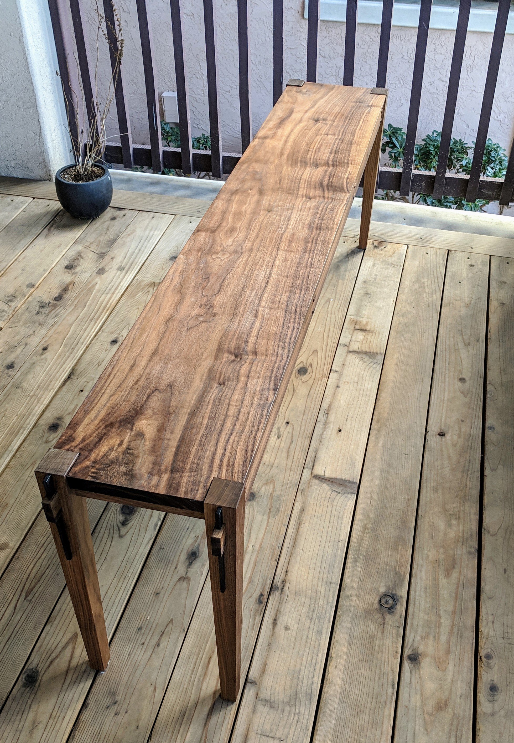
How much load will the joint see? This is for a table with aprons under the top, not a stretcher lower on the leg. If someone lifts one end and drags the table, then the joint would be about 30 inches above the floor. If we assume a grippy, carpeted surface, we might apply as much as 0.3*120*30=1080 inch pounds of torque to the joint. (120 pounds is about 1/2 the weight of this table). So let us aim for a joint which can handle, say, 1500 inch pounds. That ought be pretty bomb-proof. (A stretcher might be 12 inches above the floor, but would also carry more of the tables weight. So 2000 in-lbs should be OK for it, too.)
Now, I am ignoring the ability of the tenon to bear against the mortise in the leg – that’s deliberate. It means a well fit joint is actually a bit stronger than what I’m calculating – and that if the fit is a bit loose, it’s will still hold up. More importantly, it means driving the wedge into the joint is unlikely to split or dent the members.
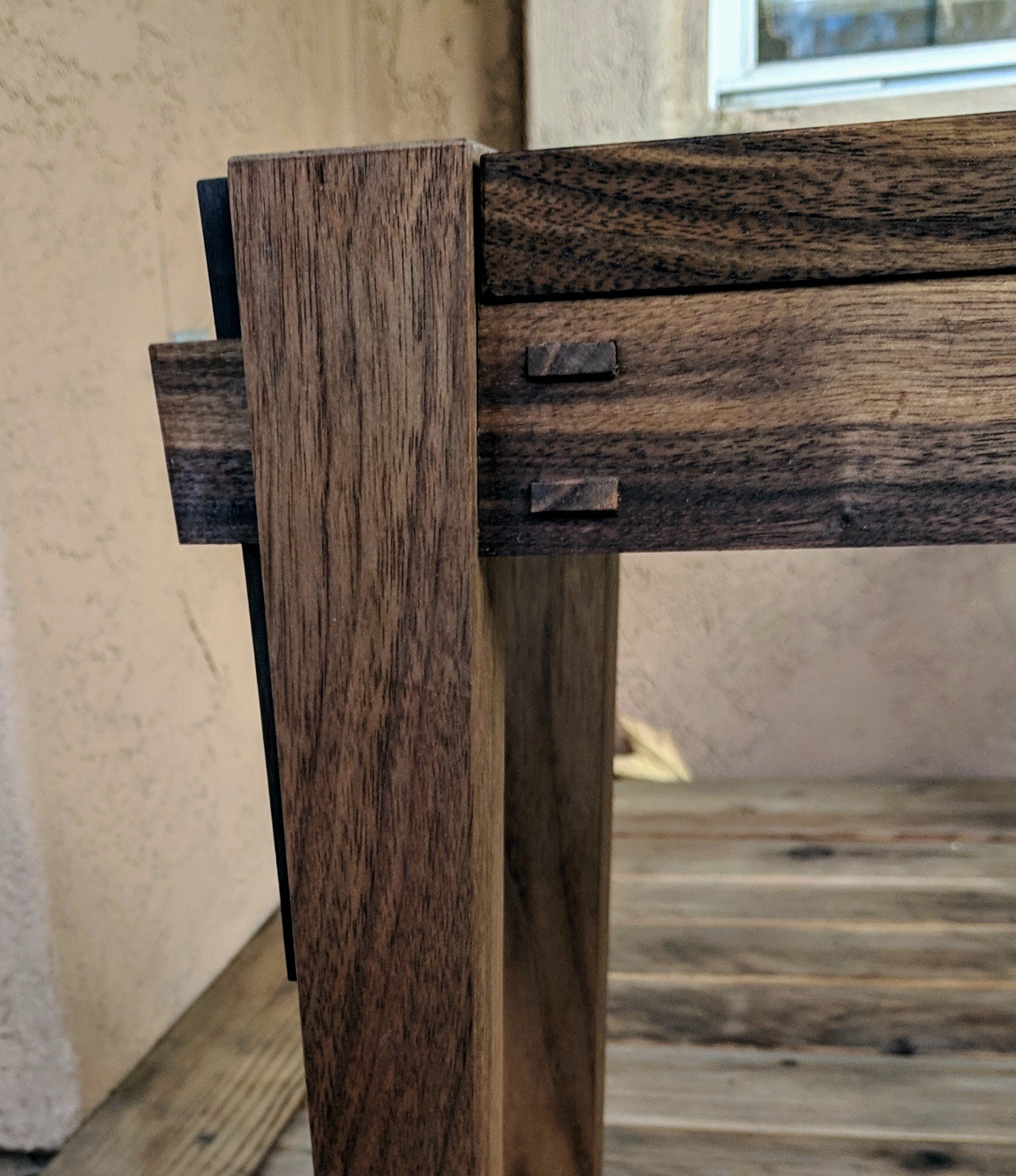
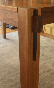
One side of the tenoned rail is pressed against the leg, and the other tries to pull out of the leg, resisted by the wedge (in shear). The compressed shoulder of the tenon bears against the leg, so it needs a bit of area to do that – it’s not just cosmetic. Then again, the height between the compressed shoulder of the tenon and the shearing side of the wedge should be substantial too. That reduces the load by spreading it out. Similarly, we want the wedge to have some bearing area on the leg and on the wall of it’s own mortise – so it should extend a fair ways beyond the tenon, perhaps thrice it’s width. And mortise wall shouldn’t be less than that either.
As a first estimate, cut the wedge mortise to be, say, 1/3rd or 1/2 the thickness of the tenon. The wedge should be somewhat square-ish where is exits the tenon underside, and extend a fair ways beyond the tenon. The tenon will probably be about 3 times taller than it’s width, and the uppermost shoulder of the tenoned member would be another, say, 1/2 wedge thickness all around. And assume the leg is simply big, in all dimensions.
At a guess, the tenon should extend perhaps three times the wedge thickness beyond the wedge mortise. This dimension will be key to ensuring the joint holds up. (And it’s the one which I haven’t found much advice about.)
So if the wedge width is T, then our guesses lead us to something like :
- The wedge is TxT wide and thick at the exit through the tenon. It extends about 3T beyond the tenon.
- The tenon is 3T x 9T, extending about 3 T beyond the wedge.
- The shoulder of the tenoned member is more like 4T x 10T or 6T x 10 T.
Time to solve for T.
Mr. Fukuyama’s equations
Equation 2 looks a bit forbidding. Time to fire up Google Sheets.
Some values for the strength of the wood are needed – walnut, in my case. Sources :
Between the two we can find the properties needed.
Here is the spreadsheet : Single Shear Wedge
So, answers, for the first pass geometry, using walnut, and T=.375 inches :
| Failure Load |
|
Lb |
N |
| Bearing failure of Leg |
Eq 2.1 |
426.1 |
1895.4 |
| Bearing Failure of Tenon |
Eq 2.2 |
2982.7 |
13267.5 |
| Mode 3 |
Eq 2.3 |
636.6 |
2831.5 |
| Mode 4 |
Eq 2.4 |
299.1 |
1330.3 |
| Mode 5 |
Eq 2.5 |
650.0 |
2891.2 |
| Mode 6 |
Eq 2.6 |
414.2 |
1842.4 |
| Shear of Wedge |
Eq 2.7 |
398.0 |
1770.3 |
| Shear of long grain in tenon (blowout) |
|
578.0 |
2570.9 |
| Transverse bearing limit of leg |
|
805.7 |
4738.4 |
Well that’s gratifying. It seems the tenon is more than long enough to avoid blowout at 578 vs. 299 (though I will take that with a grain of salt). It’s not at all surprising that the tenon (end grain) is stronger than the leg (transverse grain). As expected, combined shear/bending/partial bearing failure (Mode 4) is limiting (in english : the wedge will bend a bit, and dent the leg below the tenon on the wedge side).
299 pounds gives some 1065 inch pounds of load before failure. A little more is desired, but the guesses were close.
Adjust all the proportions a bit, and account for other design constraints. Here’s a final result:
| Failure Load |
|
Lb |
N |
| Bearing failure of Leg |
Eq 2.1 |
568.1 |
2527.1 |
| Bearing Failure of Tenon |
Eq 2.2 |
3976.9 |
17690.0 |
| Mode 3 |
Eq 2.3 |
848.7 |
3775.4 |
| Mode 4 |
Eq 2.4 |
438.9 |
1952.4 |
| Mode 5 |
Eq 2.5 |
884.8 |
3935.8 |
| Mode 6 |
Eq 2.6 |
621.3 |
2763.6 |
| Shear of Wedge |
Eq 2.7 |
597.0 |
2655.4 |
| Shear of long grain in tenon (blowout) |
|
578.0 |
2570.9 |
| Transverse bearing limit of leg |
|
751.7 |
4316.2 |
Which gives a maximum torque of 1399 lb-inches, and an adequate tenon (578 vs 438 pounds). Proportions chosen :
| Proportion |
|
|
Inch |
Metric |
| 1 |
Wedge width |
|
0.375 |
9.53 |
| 1.5 |
Wedge thickness |
|
0.563 |
14.29 |
| 3.333 |
Width across shoulder |
|
1.250 |
31.75 |
| 9 |
Height across shoulder |
|
3.375 |
85.73 |
| 2.25 |
Tenon width |
|
0.844 |
21.43 |
| 8 |
Tenon height |
|
3.000 |
76.20 |
| 2 |
Tenon Length beyond wedge mortise |
|
0.750 |
19.05 |
| 4 |
Wedge length (protrusion) |
|
1.500 |
38.1 |
Solving it again, same geometry but using silver maple :
| Failure Load |
|
Lb |
N |
| Bearing failure of Leg |
Eq 2.1 |
416.3 |
1851.6 |
| Bearing Failure of Tenon |
Eq 2.2 |
2913.8 |
12961.0 |
| Mode 3 |
Eq 2.3 |
595.2 |
2647.6 |
| Mode 4 |
Eq 2.4 |
321.6 |
1430.5 |
| Mode 5 |
Eq 2.5 |
648.3 |
2883.7 |
| Mode 6 |
Eq 2.6 |
413.6 |
1840.0 |
| Shear of Wedge |
Eq 2.7 |
1336.3 |
5944.1 |
| Shear of long grain in tenon (blowout) |
|
624.4 |
2777.4 |
| Transverse bearing limit of leg |
|
710.9 |
3162.4 |
Maple is a bit weaker – 321 vs. 438 pounds – which is expected. That gives about 1000 inch-lbs of torque before denting. The proportions and resulting failure are the same, and especially, the tenon is still long enough to not blow out (624 vs 321). In fact, maple is better than walnut for that – 1480 psi vs. 1370 psi, so the tenon could be a touch shorter.
Grain and orientation
Ok, I’ve dug into grain orientation a little more, based on Brian’s thought provoking comments.
The tests are conducted such that the compressive load is applied “to a radial plane”, and the bending load is applied perpendicular to that. That’s buried deep into the ASTM D143 spec covering the tests.
This paper covers the results of some tests, and shows clearly that the stiffness is slightly higher at 90 degrees than at 0, for larch. This paper is for chestnut, and shows the same behavior – but included strength limit data as well. And this shear test paper includes shear test data. These first three clearly show the compressive strength and stiffness is higher if the forces is against faces which are tangential to the radial grain (and not against a radial face). That said, Bruce Hoadley wrote a book and on page 82 he suggests exactly the opposite, at least for ash and ring porous hardwoods. This blog post would seem to agree. Hankinson’s formula does not consider radial vs. tangential grain orientation.
The US Forest Service addresses this (page 40-30 and 4-31). They suggest that, depending on species, either 0 and 90 degrees are about equal, or that 90 degrees (radial) is a bit stronger.
I’m afraid I haven’t yet found a clear guideline, aside from staying near either 0 or 90 degrees, and avoiding the intermediate orientations. Which is to say, either rings running from shoulder to wedge, which matches my calculation, or perpendicular to that. In either case, the calculation I did should be close.
Proportions and Conclusions
That all leads to some rules of thumb.
- The wedge is T wide and 1.5 T thick at the exit through the tenon. It extends about 4T beyond the tenon.
- The tenon is 2T or 3T by at least 8T, and extends at least 2 T beyond the wedge.
- The shoulder of the tenoned member is more like 3.33T x 9T
- And for an application like a dining table, T is at least 3/8ths of an inch [9.5mm].
Now, aesthetics may lead to a somewhat different solution, and of course some applications may need less strength. As long as you follow the proportions here, then the wedge should still fail first.
If the wedge is thicker, say 1T x 2T, then the leg will dent a bit more. If it is thinner, as in the first pass, then the wedge is a bit flimsy. A wider wedge would be worth considering, but I don’t have a wider mortising chisel, and the resulting tenon width does not suit the available stock.
I haven’t tested this in practice, so some caution is warranted. It’s all theory. But I think I did it right. Comments, feedback, and someone checking my work is all welcome !
I hope that was helpful for some of you, feel free to ask questions.
That’s all folks!
A part two is here.